3D Printer Calibration Guide using IdeaMaker
For proper 3D printer calibration, you need to have access to the printer’s EEPROM. In this article, I will show you how to do your 3D printer calibration with IdeaMaker.
Some of the printers have the EEPROM locked and they don’t allow saving new values. By adding the calibration values right in IdeaMaker you can mitigate this issue.
Doing your 3D printer calibration with IdeaMaker has the benefit of not needing to edit your EEPROM because all the values are set right in the slicer. Each time you slice a model, the calibrated values are stored in the G-Code and are applied at the start of your print.
In case you don’t know about IdeaMaker, make sure you check my IdeaMaker review where I cover a few of my favorite features it has.
Prerequisites for 3D printer calibration
Before starting the 3D printer calibration with IdeaMaker, it’s important to make sure that every mechanical part of the printer is running correctly.
I will publish an exhaustive guide soon, but until then, you can check the Sidewinder X1 Calibration guide where I described most of the points to check for a 3D printer. Even though the guide is written for the Sidewinder X1, most of the 3D printer calibration information applies to any other printer.
Take your time and check everything carefully, because if the mechanical movement of the printer is not right, your calibration will not bring the expected results.
3D printer calibration steps
Extruder Calibration
The first thing I do for any of my 3D printers is to calibrate the extruder.
Besides making sure every mechanical part is running correctly, calibrating the extruder is one of the most important things to do during the 3D printer calibration process. By calibrating the extruder, you make sure that the amount of filament requested by the printer is the same as the amount of filament extruded.
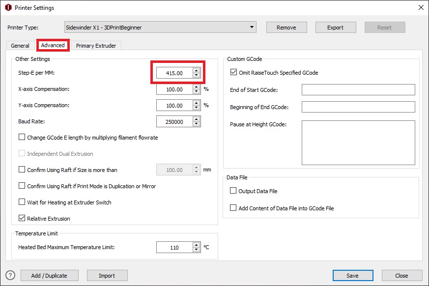
I covered the whole extruder calibration process in this article. After you get the calibrated value, you need to enter it in IdeaMaker.
This is under Printer settings -> Advanced -> Step-E per MM.
Flow Rate Calibration
Now that you calibrated the extruder and the extrusion is consistent, you need to calibrate your flow rate. The flow rate is another important 3D printer calibration step. It’s calibrated for each type of filament you are printing. Most of the time, the values between filaments are not that different, but for best results it’s recommended you calibrate the flow rate for each filament type and manufacturer.
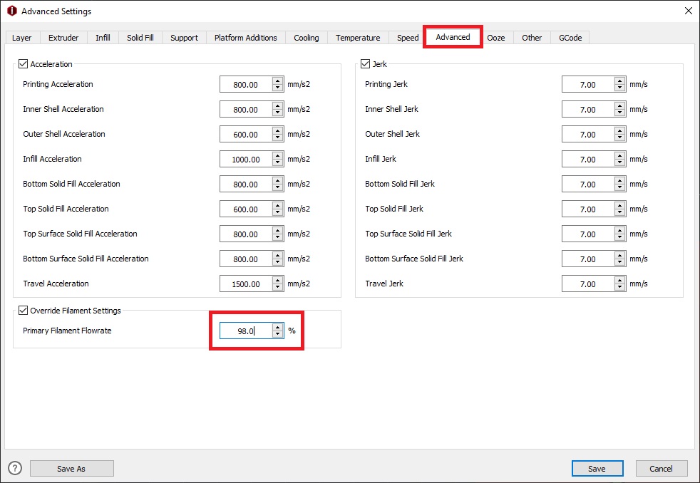
To do this, follow my flow rate calibration guide. After you get the calibrated flow rate for your specific type of filament, head over to IdeaMaker and update the flow rate value inside the slicer.
This is under Template Settings -> Advanced -> Primary Filament Flowrate. Make sure the Override Filament Settings is checked.
Temperature Calibration
With the extruder and flow rate calibrated, it’s now time to do a temperature calibration. Each type of filament has a “sweet-spot” where it prints best. On some filaments, even the color can have an impact on the temperature where it prints best.
For some filaments, you can also change the finish you get just by adjusting the temperature. I have a spool of Sakata Black PLA which has a matte finish when printed at 195C which turns in a glossy black when printed at 215C.
The temperature calibration is ignored most of the time, even though it’s just as important in the 3D printer calibration process, for good quality prints.
What we are trying to achieve with this calibration is to have the best combination of layer adhesion and print quality. After calibrating the temperature, you will be able to assess the best temperature which can be used for your models.
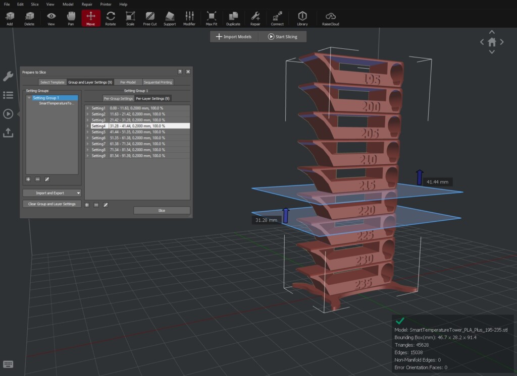
To do that, we need to generate a temperature calibration tower in IdeaMaker which will instruct the printer to change the hotend temperature for each level.
All you have to do is download the Temperature Calibration Tower idea file I prepared, open it in IdeaMaker then slice it with your machine profile.
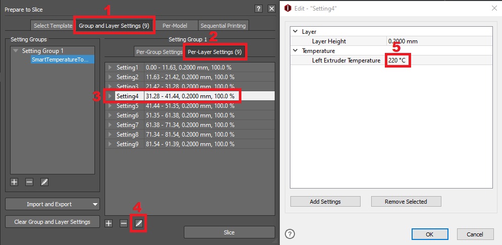
The model is set to start with 235C and lower the temperature until it reaches 195C. You can alter the settings I used in the Per-Layer Settings section.
To update the hotend temperature, navigate to Advanced settings -> Temperature -> Primary Extruder.
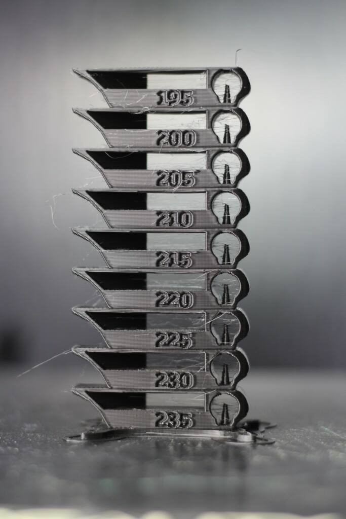
Below, you can see the temperature calibration tower printed on the CR-6 SE. The first few sections printed from 235C to 215C look shiny and the others gradually become matte.
The whole idea is to choose the section which looks best and has the most detail. For this filament, I chose 200C because it looks best. You should ignore the small wisps if retraction is not set right. We will calibrate this in the next step.
Retraction Calibration
We can now properly calibrate the retraction. It’s important to do this step after calibrating the filament temperature to ensure consistent results. The retraction values can change according to temperature so it’s better to do this at the end.
Retraction movements are performed by the extruder to minimize the pressure inside the hotend. If there is no pressure inside the hotend, molten filament leaks from the nozzle only because of gravity.
Your retraction value will also be influenced by the quality of the heat break used in your hotend. A bi-metal heat break can improve retractions significantly in some situations.
Bowden setup
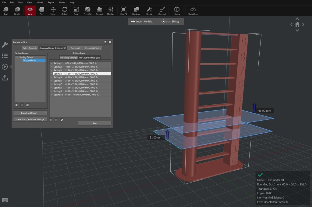
Download the Retraction Calibration Tower I prepared, open it in IdeaMaker then slice it with your machine profile.
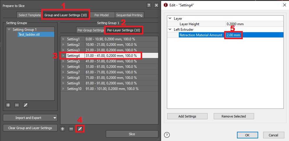
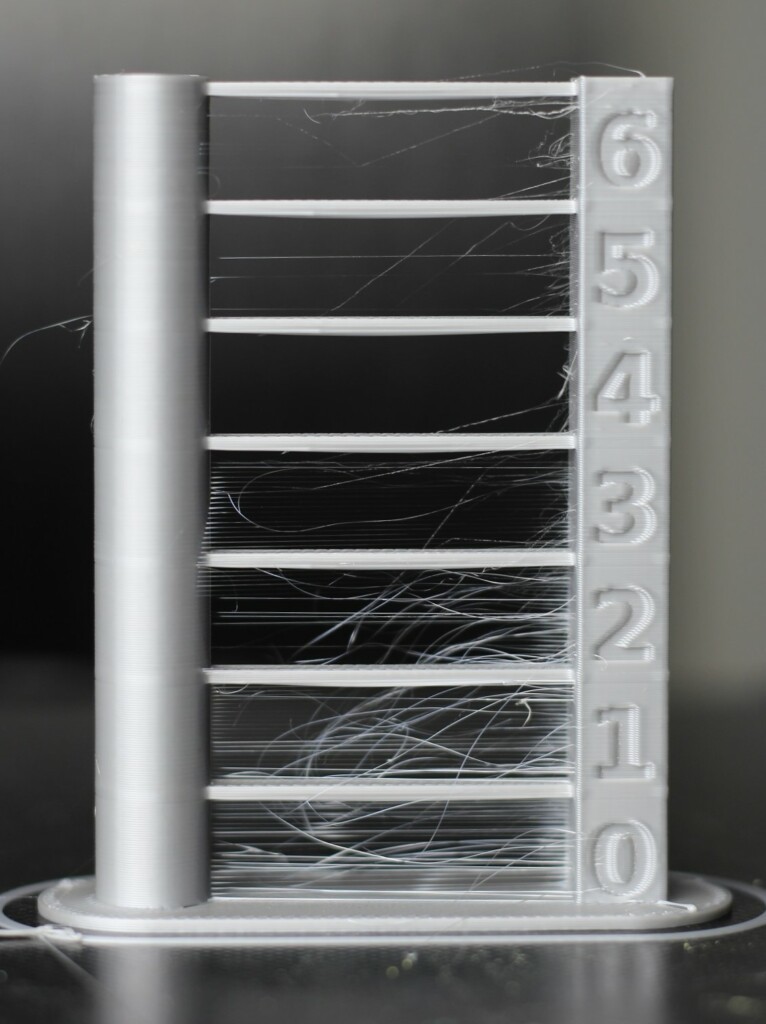
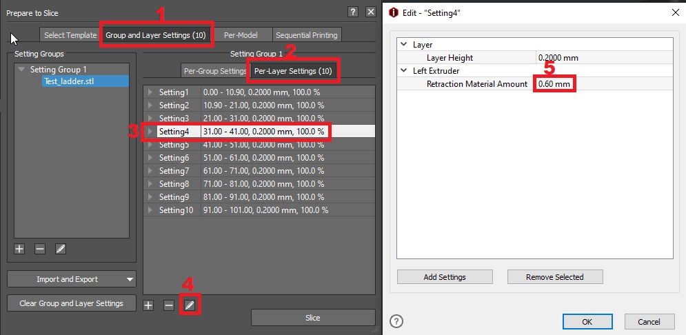
The model is set to start with a retraction value of 0.5 mm and increases with 0.5 mm increments until it reaches 5 mm. You can alter the settings I used in the Per-Layer Settings section.
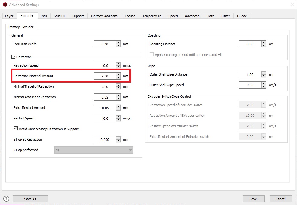
To update the retraction value, navigate to Advanced settings -> Extruder -> Retraction Material Amount.
As you can see in my test below, a retraction value of 2.5 mm works well. This is on the Creality CR-6 SE. I stopped the print at the 6th level because I found the value which works best before the print ended. Your results might be different.
To further tune your retraction setting and eliminate the remaining stringing present on the model, you can also add a bit of coasting.
The coasting value tells the printer to stop extruding for the set value, just before printing a line. This way, the remaining pressure inside the nozzle will push a bit of filament rough the nozzle even though the extruder is stopped.
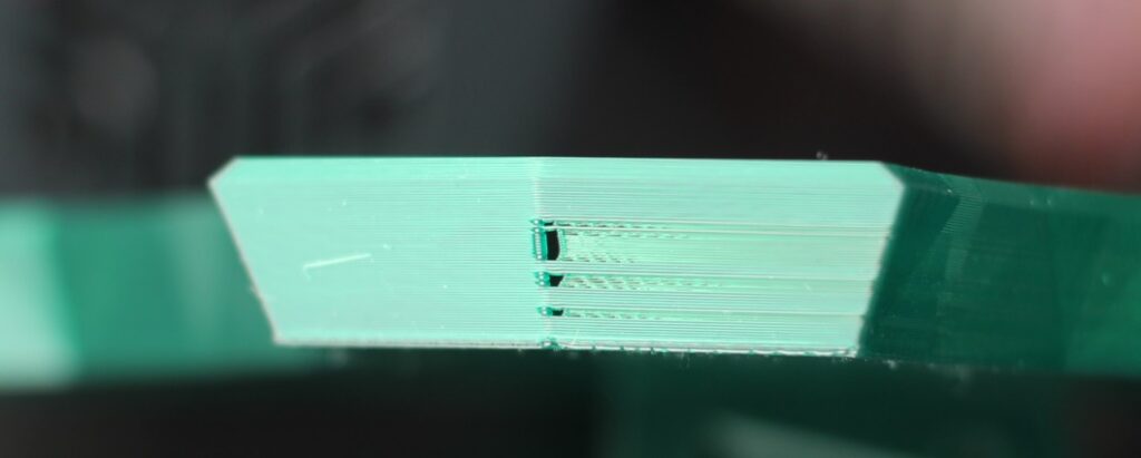
As a rule of thumb, for bowden setups I use a value between 0.2mm and 0.4mm of coasting which usually works great, but if you see under-extruded portions next to the Z seam, then lower the value until it disappears.
Here’s an example of a coasting value set too high in the slicer.
To update the coasting value, navigate to Advanced settings -> Extruder -> Coasting Distance. Make sure you also enable the Apply Coasting on Grid Infill and Lines Solid Fill setting.
Please be advised that if you are using Pressure Advance or Linear Advance, coasting can interfere, and you might get bad results. If you have any of these features available, it’s recommended to leave the coasting value set to 0.
Direct Drive setup
If you are calibrating a direct drive extruder, then you need to update the retraction values. As you probably know, direct drive extruders need much less retraction compared to a bowden setup (something between 0.2mm to 2mm).
Calibrating retraction with the previous file will result in clogging your hotend. I prepared a Retraction Calibration Tower for Direct Drive which you can use.
The model is set to start with a retraction value of 0 mm and increases with 0.2 mm increments until it reaches 1.8 mm. You can alter the settings I used in the Per-Layer Settings section but if you need to go over 1.8 mm then something is wrong.
For good direct drive extruders, coasting does not bring too many benefits because the pressure inside the nozzle is low. You can still use a small amount if you are running a high flow/volcano nozzle. But keep it off if you are using Pressure Advance or Linear Advance.
Fine tuning
With all the major 3d printer calibration steps done, you can start fine-tuning your slicer settings to fix other small issues which can show up on your prints
Top and bottom layer flow rate
If your flow rate is well calibrated, your top and bottom layers should look great. But there are some time where you might find signs of over extrusion or under extrusions on your 3D printed models.
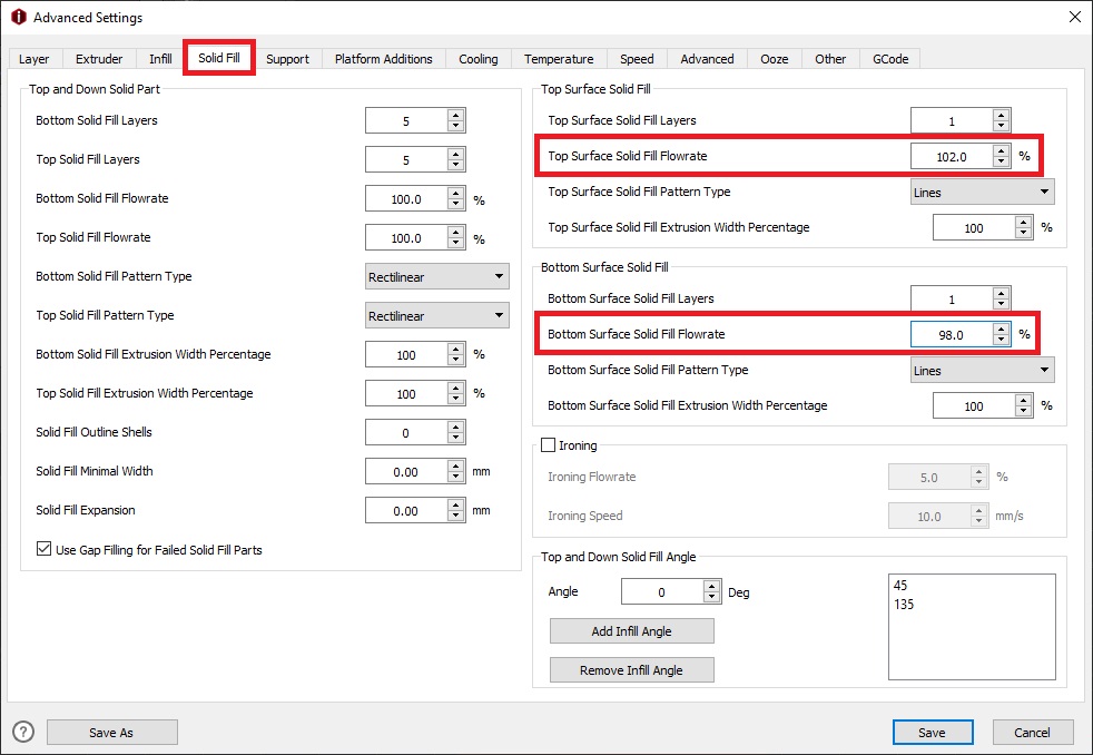
This issue can be mitigated by changing the flow rate of your bottom or top layer flow rate.
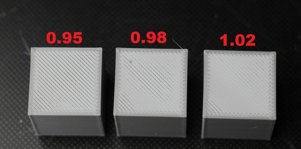
To have a starting point, I recommend you print a calibration cube. After the print is finished, check the quality of your top and bottom layers. If they are over-extruded, you need to lower to the top layer flow rate in IdeaMaker.
In the image below, you can see how different values change the print quality of the top layer. A value of 1.05 will probably make the top surface look best.
Lowering the flow rate on for the bottom layer can also mitigate the elephant’s food effect you get when your nozzle is too close to the bed of if the extruder is pushing too much filament on your first layer.
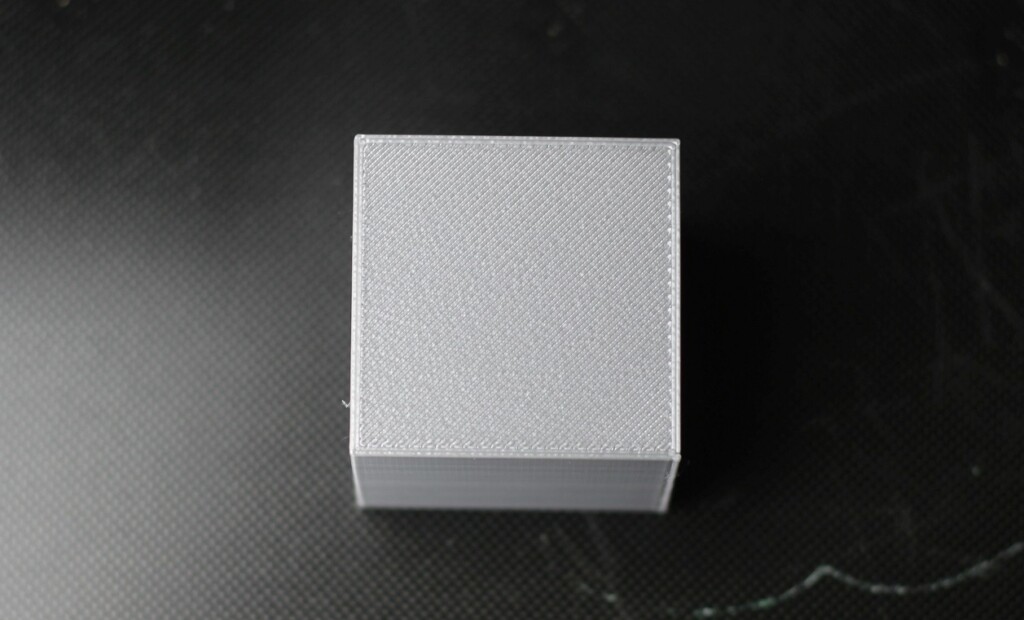
If the bottom layer is over-extruder or under-extruded then you need to edit the bottom layer flow rate in IdeaMaker until it looks good. Below you can see an example on how the bottom layer should look like.
X and Y compensation
With the calibration cube printed right, you can now measure it to make sure it has the correct dimensions on the X and Y axis.
Most of the time, after making sure your belts are tight, and the extruder is properly calibrated, your print size dimensions should be really close to what you are expecting.
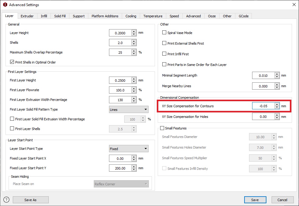
If this doesn’t happen then you can calibrate IdeaMaker to compensate for the differences you get on your finished prints by editing the XY Size Compensation for Contours value.
For accurate results, I recommend printing a 40×40 calibration cube (I scaled the regular calibration cube to 200%). Next, measure it on the X and Y axis and compare the results with the desired dimensions.
Don’t measure right on the top or the bottom of the print because you can have different dimensions caused by the solid layers.
For example, let’s say your calibration cube has a dimension of 40.1 mm on X and Y. To compensate for this, enter 0.05mm in the the XY Size Compensation for Contours section. This will compensate 0.5mm on each side.
Finally, print a cube with the calibrated values set up, and do a final measurement. The cube should have the expected dimensions.
To update the XY Size Compensation for Contours, navigate to Advanced settings -> Layer -> XY Size Compensation for Contours.
Fix hole dimensions
Even if your 3D printer is properly calibrated, sometimes the holes of your printed parts can be smaller than designed. This can be caused by material expansion or small variances in the extrusion.
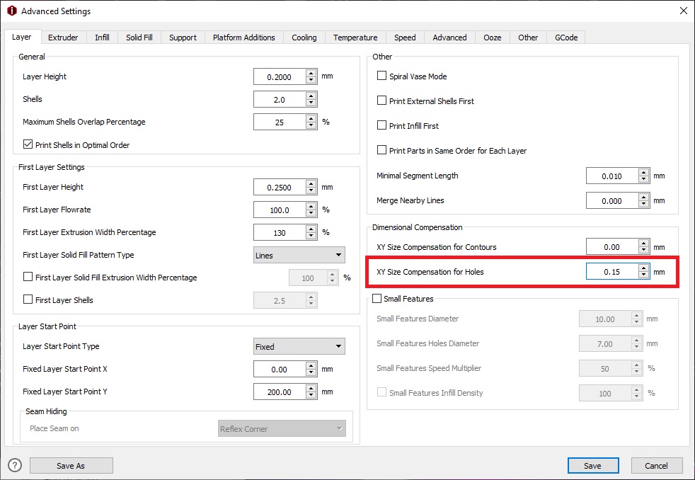
You can use the XY Size Compensation for Holes feature in IdeaMaker to fix this.
The best way to do it is to first print a model as a reference. After the model is printed, you should try to insert a known size part through the printed hole.
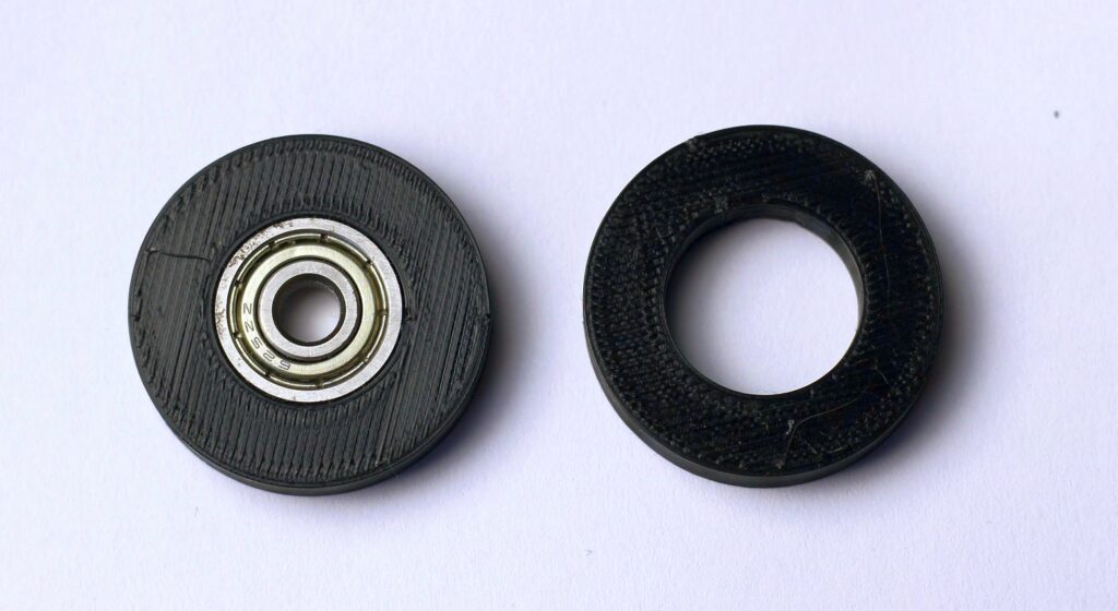
My go-to test print is a simple hole test I made in Fusion360 with a diameter of 16mm. To test if the printed hole is accurate, I try to push-fit a 625ZZ bearing (same one used on V-roller wheels).
If the bearing fits in the printed hole test, then your printer is properly calibrated.
If not, increase or decrease the XY Size Compensation for Holes value until the bearing fits.
To update the XY Size Compensation for Holes, navigate to Advanced settings -> Layer -> XY Size Compensation for Holes.
Z seam calibration
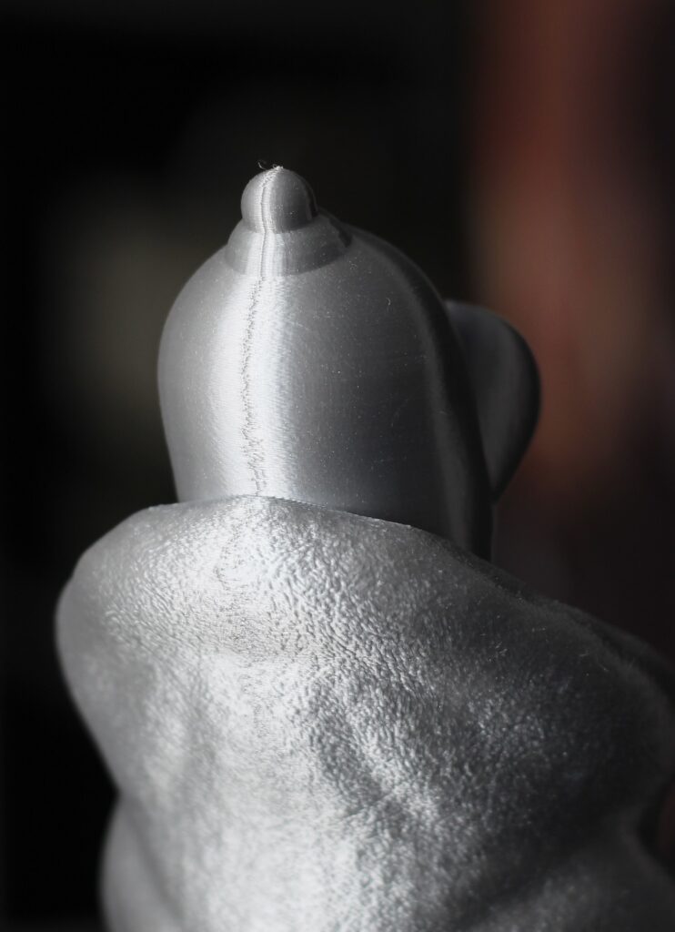
In case you didn’t know, you can also calibrate the Z seam. This is the position where a new layer starts and finishes. Unfortunately, you cannot completely remove it (besides vase mode) but with some fine tuning, you can make it less apparent.
First, you can use a wipe movement during the end of a layer which tries to “glue” the layers and make the seam less vizible.
Finally, you can adjust the position of the Z seam on a less visible part of the model (in the back, or on a corner). You can control this by adjusting the Layer Start Point in IdeaMaker.
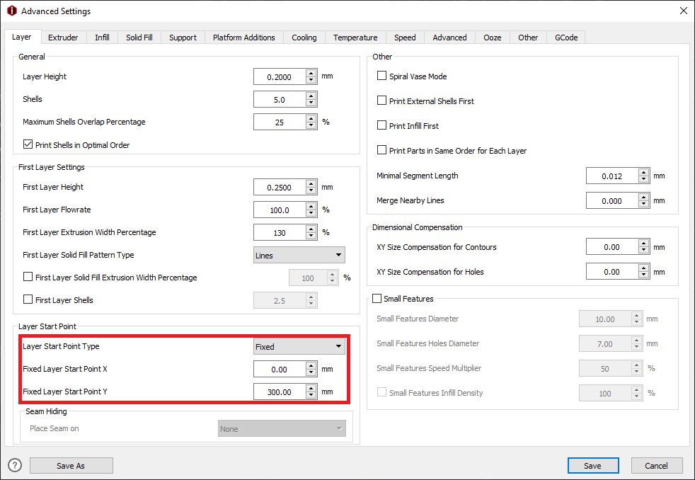
I always set my Layer Start Point Type to Fixed, and manually set the Z seam position on the X and Y axis by entering a fixed coordinate.
For example, when I want to set the Z seam in the back of the model, I set the Fixed Layer Start Point X at half the size of the bed. In the case of a bed with 300mm x 300mm, I set it to 150.
For the Fixed Layer Start Point Y, I set it at the highest position of the Y axis. In this case, 300.
To update the Z seam position, navigate to Advanced settings -> Layer -> Layer Start Point.
Wrapping up
If you carefully followed all the steps in this 3D printer calibration guide, your prints should look great and the dimensions should also be accurate.
You might also want to learn how to dry your filament if you still have bad quality prints.
If you have questions, feel free to leave a comment below and I will try my best to help you. You can also join the 3DPrintBeginner Forum where there’s a dedicated IdeaMaker thread for discussions.
Liked it?
|
|

