Artillery Linear Rail Y Axis Mod Guide: Sidewinder X1 and Genius
Have you ever struggled to get the roller wheels under your printer bed adjusted *just* right? Are you noticing a bit of wiggle creeping in to your Y axis after printing on it for a year or two? If so, the time might be right to upgrade to a linear rail motion constraint. I just did on both my Genius and Sidewinder X1, and it turns out to be a pretty straightforward process.
Why linear rails?
Most budget 3D printers these days use an aluminum V-slot extrusion / roller wheel motion constraint on each axis. There are some real advantages to this system: it is inexpensive to manufacture, quite forgiving of minor imperfections in alignment and part quality, and plenty rigid enough for the limited loadings encountered in small FFF machines.
Linear guide rails are commonly used in machines needing precise alignment under higher loads. A ground, hardened steel rail provides the stationary bearing surface, and a steel carriage block with recirculating ball bearings provides the moving one. The geometry of the ground surfaces ensures that the carriage can only move along a single axis, and cannot wiggle or twist.
For me, the primary advantage of converting a budget machine like the Artillery Genius to use linear rails is for ease of maintenance: unlike the POM roller wheels and eccentric nuts, linear rails don’t need to be carefully adjusted to fit *juuust* right; and, if kept properly lubricated, they will not wear out or need to be replaced. You *may* also see improvements in print quality—particularly if your existing rollers are a little worse for wear—but a properly-tuned roller wheel setup will produce results every bit as good. It just won’t stay that way without a little bit of TLC. If you’d rather spend your time, say, working on other projects rather than nurturing your rollers, linear rails might be for you!
They come with some downsides, of course. Professional-grade linear rails can easily run into the hundreds of dollars each, although units of adequate quality for our machines can be had for much cheaper. And because they have very tight tolerances, very precise alignment is necessary to prevent binding, especially in applications where two rails are installed in parallel.
Parts and tools needed
Fortunately, if you already have an assortment of metric screws available, you might already have most of what you need for this mod! Adequate-quality cheap rails can be sourced on Amazon (I have had good luck with TwoTrees-branded rails) or AliExpress.
Aside from some hex wrenches and a pair of pliers, the only tools you need to complete this project are some sort of drill (a cordless drill works just fine) and a ~3.5 mm drill bit, and maybe a clamp and a piece of scrap wood.
| Part | Genius | SWX1 | Link |
| Linear rail | 1x 350 mm rail | 2x 450 mm rail | CNA Mechanical Parts @AliExpress |
| Carriages | 2x MGN12C | 2x or 3x MGN12H | CNA Mechanical Parts @AliExpress |
| M4 10mm flat-head screw | 2 | 2 | Glarks assortment @Amazon |
| M4 hex nut | 2 | 2 | Glarks assortment @Amazon |
| M3 12mm button- or socket-head screw | 4 | 4 | iExcell assortment @Amazon |
| M3 8mm button- or socket-head screw | 8 | 8 or 10 | iExcell assortment @Amazon |
| M3 20mm button- or socket-head screw | 1 | 1 | iExcell assortment @Amazon |
| M3 8mm socket-head screw | 7 | 20 | iExcell assortment @Amazon |
| M3 hex nut | 6 | 6 | iExcell assortment @Amazon |
| M3 hammer t-nuts | 7 | 20 | M3/4/5 assortment @Amazon |
Y Axis Linear Rail Mod Steps
Print parts
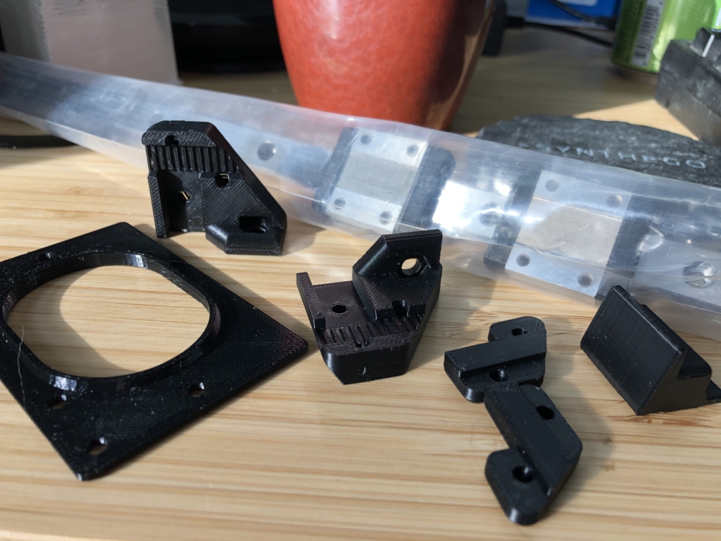
You will need a few printed parts for this mod. It is probably a good idea to print them out before disassembling your printer! Make sure to use the correct belt clamp for your printer: the hole spacing for the Genius and the SWX1 parts are slightly different.
I’ve uploaded everything needed to my PrusaPrinters.org profile. Because my parts will be living in a heated printing enclosure, I printed them in ABS for the increased temperature tolerance. PETG would be a good choice for room-temperature applications. I would avoid PLA due to its tendency towards creep under sustained loads, such as will be experienced by the belt mounts.
Disassemble Y axis and remove roller wheels
First, remove the heated bed from the Y axis carriage. Fully unscrew each of the four adjustment wheels until they’re completely off the screws. You can then carefully remove the bed and lay it off to the side. Take care not to lose the springs!
Next, remove the M5 screws holding the front Y axis idler bracket to loosen the belt, and remove it from the extrusion. Use a pair of side cutters to carefully cut the zip-ties securing the belt to the Y carriage. Now, you can slide the carriage completely off the extrusion.
To remove the roller wheel posts, use a wrench or pliers to hold the nylon locknuts above each carriage, and use a hex key to unscrew the bolt from below.
Drill holes for linear rail carriages
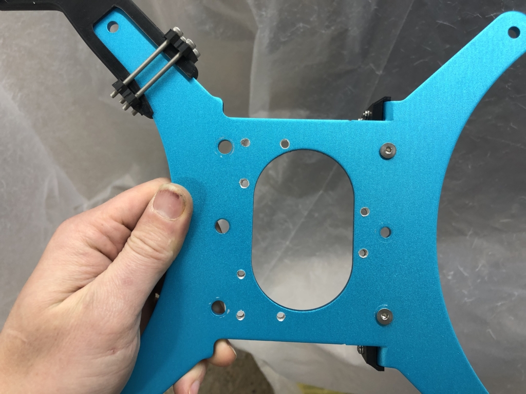
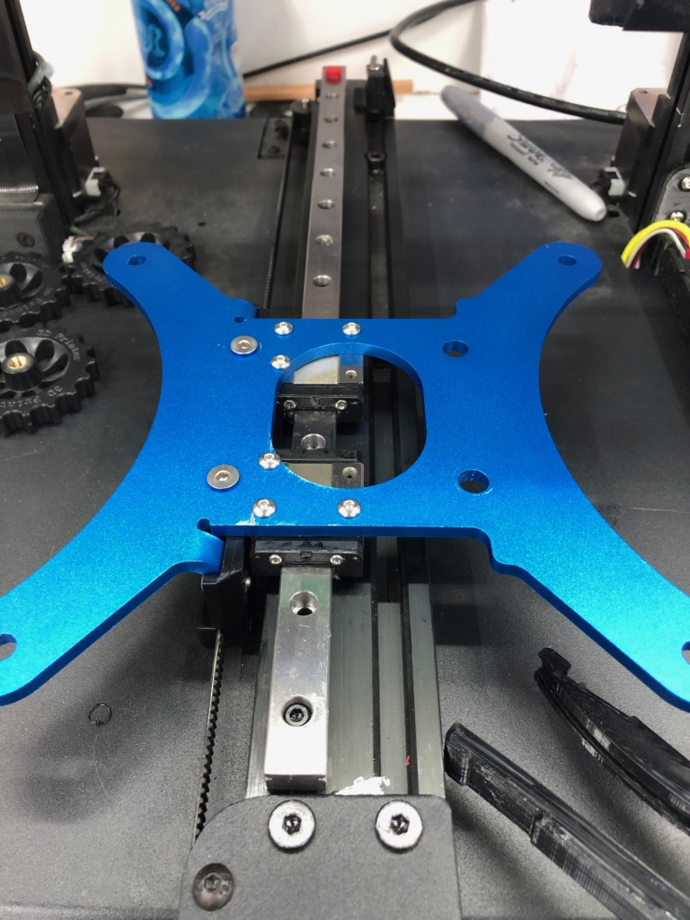
For the Genius, you should just use a single 350 mm MGN12 rail, with two MGN12C carriage blocks (the shorter ones). Print out the drill guide and align it to the aluminum bed carriage—the oval rim has a slight taper that should help it sit precisely. The holes for the MGN12C blocks should be on the left side of the carriage, closest to the belt attachments. Now, use the holes to mark and drill the three holes for each carriage. For best results, clamp the drill guide on top of the aluminum carriage and a sacrificial wooden block underneath. Use a drill bit between 3.5 and 4.0 mm in diameter: you want a little bit of play so you don’t accidentally misalign the blocks on the rail due to imprecise holes!
For the Sidewinder X1, you have more options. The drill guide reflects this, with six possible block positions indicated by indentations. A single decent-quality 450 mm rail with two carriage blocks along the center channel of the 2060 extrusion will likely be just fine—although you will only be able to affix the aluminum bed frame with two screws per block. Two 450 mm rails, with a single MGN12H carriage on each, mounted offset to one another, is probably the optimal arrangement. I happened to have had an extra carriage laying around when I did mine, so it has three. In retrospect, this arrangement probably only adds unneeded mass to the Y axis!
Assemble printed parts
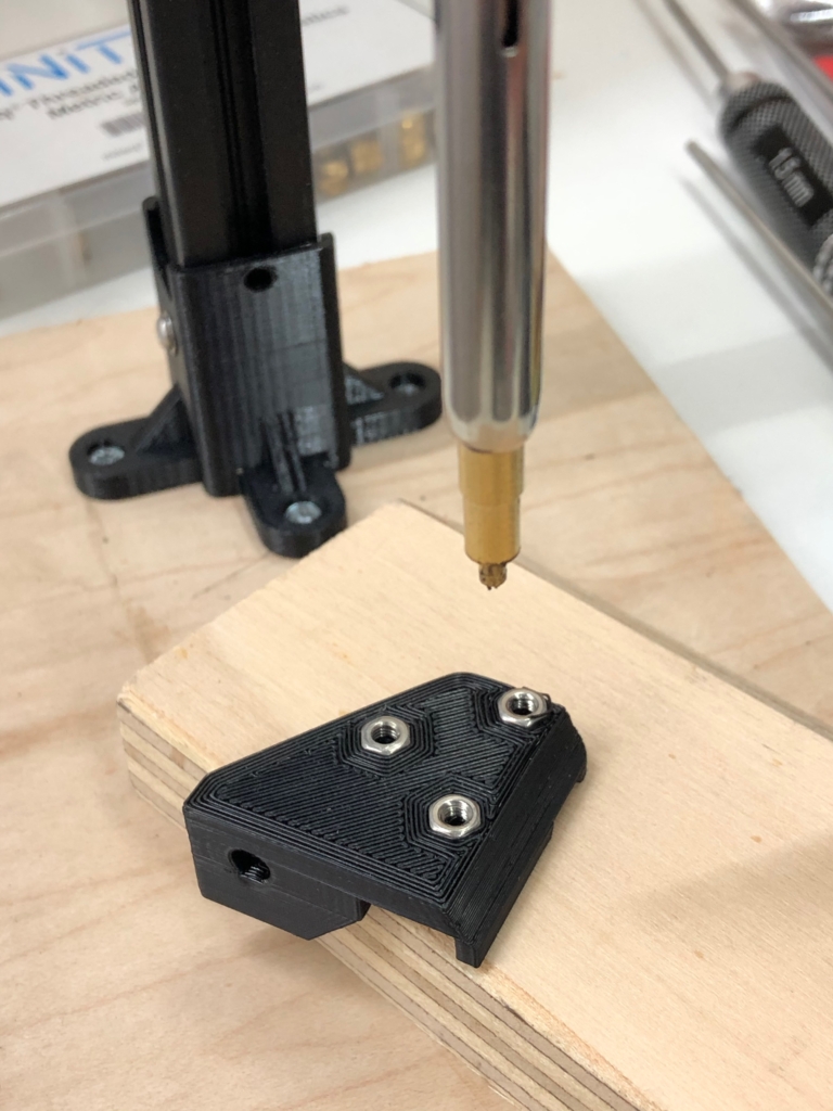
The printed belt clamps each have spaces for 3 M3 and 1 M4 hex nut. Depending on your printer’s tolerances, you may want to set the M3 nuts prior to further assembly, either by heat setting them with a soldering iron or by pulling them into the slot with a screw.
The printed belt clamps attach to the aluminum carriage at two points: with an M4 flat-head screw through one of the roller wheel attachment holes, and with an 8 mm M3 screw through the original belt slot. Loosely connect the M4 screw first, then add the M3 screw. Make sure to use a flat wash in the latter case so that the screw head doesn’t deform the belt slot. Make sure the belt clamp is flush with the aluminum and tighten down both screws.
Attach rails to frame
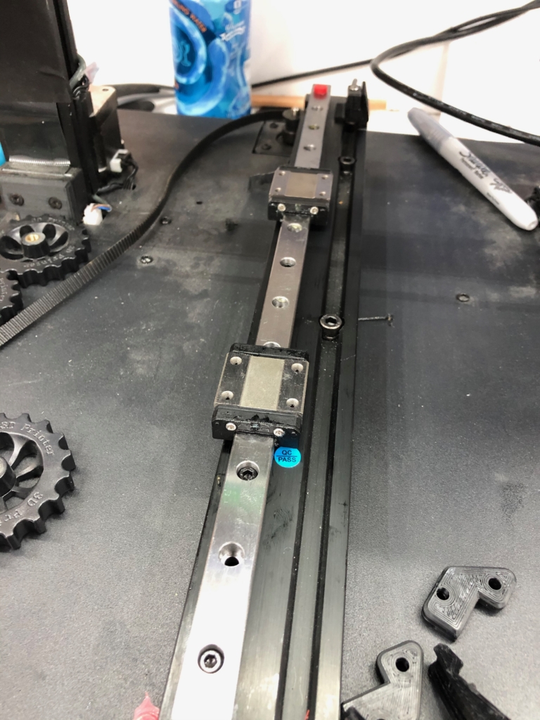
You’ll need to do a tiny modification first to ensure the rails sit flush against the extrusion: the four socket-head cap screws attaching the Y axis extrusion to the frame beneath are sitting on split-ring washers that make their tops project ever-so-slightly above the top surface of the rails. One at a time, remove a screw, get rid of the washer, and then tighten the screw back down.
Don’t skip this step. I learned the hard way…
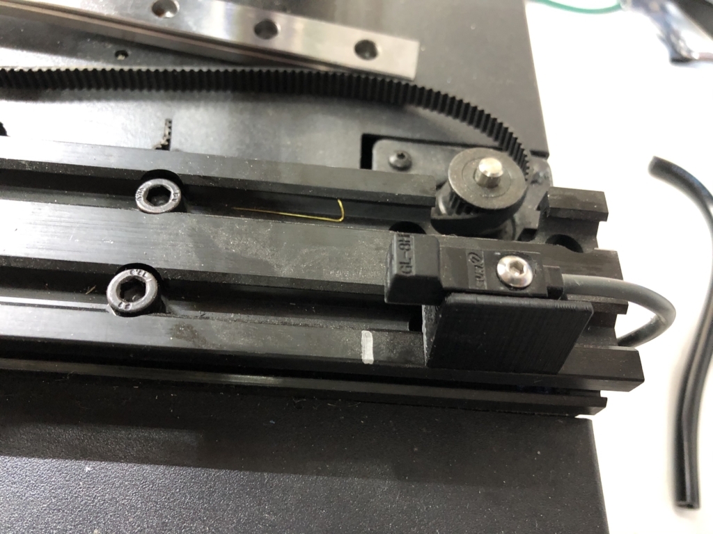
Next, make a mark on the extrusion at the face of the Y axis inductive endstop and remove it.
(If you haven’t already cleaned and lubed your carriage blocks, do it now.)
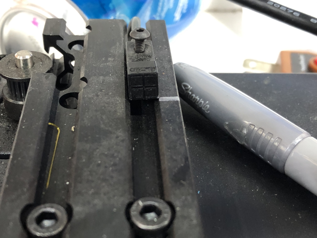
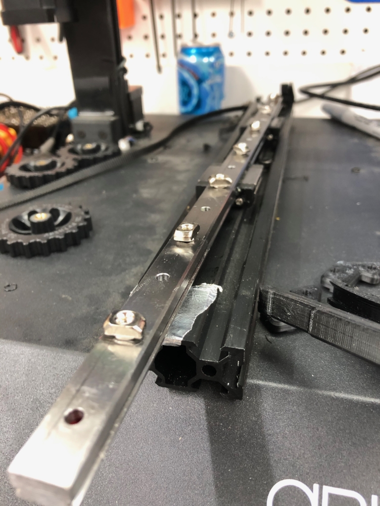
To attach your rails to the extrusions, pre-assemble them with the 8mm M3 socket-head cap screws and M3 hammer T-nuts. (Only screw the nuts on part way at this point.) I used a screw in every other hole in the rail, starting at the front. Then, place the rail over the extrusion slot and wiggle it until all the T-nuts drop down into the channel. If there are any stubborn ones, try using the end of a screwdriver to tap the side of the nut until it rotates enough to drop down. Leaving a mm or two between the front of the rail and the front belt idler bracket, tighten down each of the screws.
(It can be a little challenging to be sure each nut is grabbing. I like to go one by one, tightening each nut until I can feel the rail is secure, then backing off just a bit until the rail budges again. Then I test the next one the same way. Once I’ve verified that each nut is biting into the extrusion, I tighten them all down.)
If you’re using two rails, don’t tighten the screws on the second one all the way yet—you’ll want it to be able to move to perfectly align with the first rail in a bit.
Finally, re-install the endstop using the endstop spacer, the 20 mm M3 screw, and a hammer T-nut. Line it up with with the mark you made previously.
Attach bed carriage to rails and belt
You’re almost there! This is really the only fiddly bit.
Clamping the belt is a bit tricky. Make your life easier by doing half while the carriage is still off the bed. (I like to do the front one now.) Put the end of the belt teeth-down into the slot on the belt standoff, so that the end of the belt just barely reaches the end of the slot (you’ll want as much slack on the other side as you can have). Loosely thread two 12 mm M3 screws through the belt clamp and into the hex nuts in back. Try to tighten them down so that the belt can still move up and down in the slot, but not forward and back.
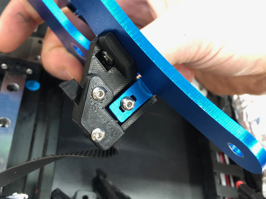
Use the remaining 8 mm M3 screws to attach the aluminum bed carriage to the rail blocks. Put them on just finger-tight at first, then grab the aluminum bed carriage and move it up and down the rails a few times to make sure everything is aligned. Now tighten the screws holding the aluminum carriage to the blocks.
If you’re using two rails, now is when you’ll want to tighten down the second one. Move the bed carriage as far forward as it will go while still exposing the first rail screw. Tighten that screw down. Now move the carriage as far back as it will go, and tighten the last screw. Alternate back and forth in this way until all the screws are tightened. If it feels like the bed travels smoothly now, you are good to go!
Finally, you can clamp the other end of the belt. Make sure it’s threaded through the extrusion slot and around both the idler and the motor pulley, then grip the very end of the belt in needle-nose pliers with one hand, and pull it reasonably tight against the teeth in the belt slot. Ideally, you can use your other hand to press the clamp against the back of the belt and those teeth will keep the belt from moving while you thread the 12 mm M3 screws in to their nuts. If that doesn’t work, you might try and retain the services of a third hand to help out. 🙂
The belt slots are designed to have a little bit of vertical play to ensure the belts can be clamped in perfect alignment with the pulleys. If it looks like the belt is riding high or low on the pulleys, you can try loosening the clamps screws a bit and nudging the belt up or down until it is parallel.
Reinstall bed and test
If everything looks good and you’re getting smooth motion of the bed carriage across the whole Y axis, you can now reinstall the bed and make sure everything still works!
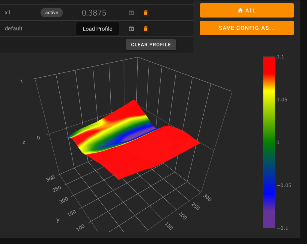
If you use an ABL sensor, you should basically be good to go at this point—do your standard routine of manual corner screw adjustment followed by ABL tweaking.
If you use the stock Z endstop, you must move it up before homing to avoid a crash. Installing rails raised the bed by a few mm, so you need to raise the endstop to compensate. Grab a spare t-nut and 8mm M3 screw, and you’ll be able to position the sensor anywhere along the slot you choose. There are various ways to do this, but I like to manually level the corners first with the machine off, by turning the Z screws by hand until the nozzle is just a mm or so above one of the bed screws. Then I move the hotend along X until the nozzle is over the front right screw, trying by eye to use that second screw to adjust the bed corner height to keep the nozzle the same distance above the bed. Repeat for each corner until things feel about level, and finally move the endstop sensor until it’s about a mm away from the X gantry extrusion. You should now be able to proceed with manual leveling as usual.
Celebrate!
You did it! Your printer now has a rock-solid Y axis, which shouldn’t need any maintenance or adjustment beyond the occasional wipe down with a clean rag and an occasional re-lubrication. Enjoy!
This is a guest post made by whoppingpochard, an awesome member of the 3DPrintBeginner Discord Server. If you also want to contribute with information, send me an email.
Liked it?
|
|



Does this work for the x2 too?
Do you have instructions for doing the x axis upgrade? That’s where my problem is.
I like how this was step by step
Better print results?